Tips and Tricks
Proportional Editing
When working with dense geometry, it can become difficult to make subtle adjustments to the vertices without causing nasty lumps and creases in the model’s surface. When you face situations like this, use the proportional editing tool. It acts like a magnet to smoothly deform the surface of the model, without creating lumps and creases, by modifying unselected vertices within a given range, not just the selected ones.The Proportional Editing mode menu is available in Edit mode, on the 3D View header.
| Off (O) | Proportional Editing is Off, only selected vertices will be affected. | On (O if off or Alt+O) | Vertices other than the selected vertex are affected, within a defined radius. |
| Connected (Alt+O) | Rather than using a radius only, the proportional falloff propagates through connected geometry. This means that you can easily proportionally edit the vertices in a finger of a hand, without affecting the other fingers, since although the other vertices are nearby spatially, they are far away following the topological edge connections of the mesh. The icon will be cleared (grey) in the center when Connected is active. |
| Falloff | While you are editing, you can change the curve profile used by either using the Mesh/Curve > Proportional Falloff submenu, using the toolbar icon (Falloff menu), or by pressing Shift+O to toggle between the various options. |
Workspace Hints
| N | Toggles Properties Shelf |
| T | Toggles Tool Shelf |
| SHIFT + Spacebar | Toggles between optimized and non-optimized view |
Vertex Editing
| Remove Vertex Point |
|
| Add Vertex Point |
|
Spin Mesh Modeling Tool
The Spin Mesh Modeling Tool is helpful for creating cylindrical shapes or anything that is consistent around a central axis.
- Go to Front View
- Press Num 5 to switch out of perpective mode.
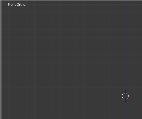
- Add mesh object like a plane. This will be the basis for the spin tool.
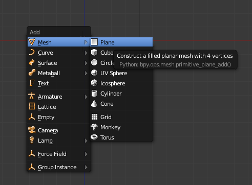
- Tab to go to Edit Mode
- Go to Top View (7)
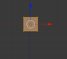
-
With the mesh selected click on the spin in the tool shelf
The default spin is 9 times with a max rotation of 90°. This means that the spin will occur in 9 incremental steps for extrusions.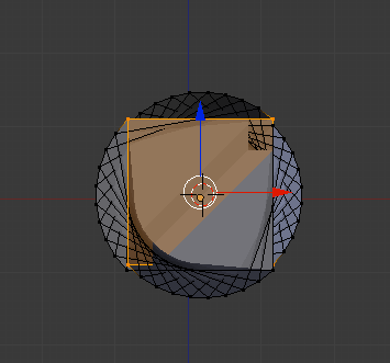
- Press F6 in Viewport after using the tool brings up the Spin Menu. You can edit the incremental steps, Dupli, center point and axis.
select Dupli to duplicate instead of extrude which keeps the steps separate. You can adjust the ° by changing the max angle.
Center Point is around the position of the 3D cursor so moving it and spinning will change your rotations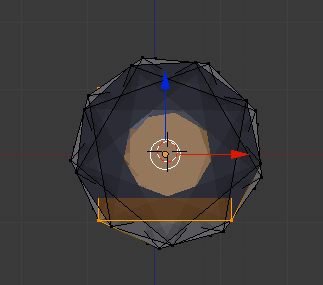
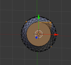
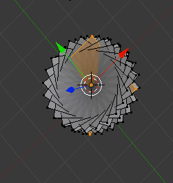
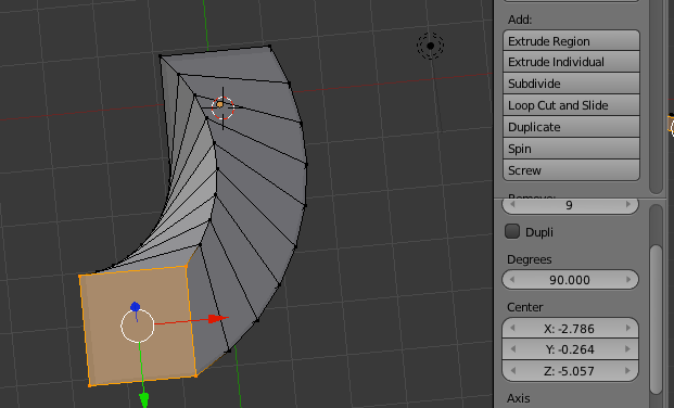
-
The default axis is perpendicular to 3D viewport
Using a Profile
- Go to Front View
- Press Num 5 to switch out of perpective mode.

- Add a mesh plane (SHIFT+A).

- Tab to go to Edit Mode
- Delete all the Vertices.
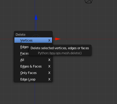
-
CTRL+LMB to add a new vertex point at the depth of the 3D cursor
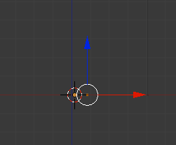
- Continue CTRL+LMB to drag out a profile
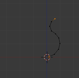
- Go to Top View (7), select all the vertices, and spin
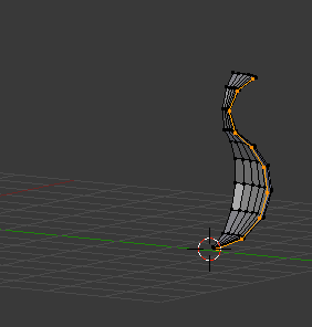
- Open up the Spin Menu and adjust rotation to 360 and segments to 16
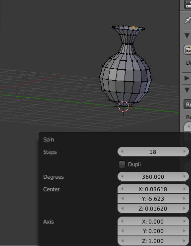
- You will have an extra set of vertices
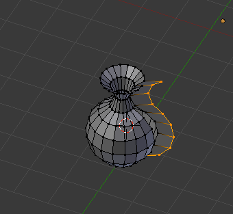
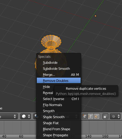
- Select All and press W to remove doubles
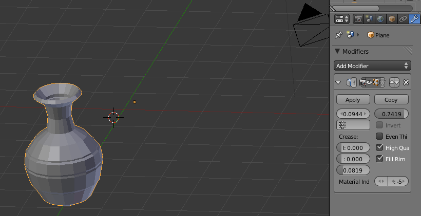
- Add Modifiers:
solidify modifier to add thickness
- Adding columns with spin
-
Add cylinder. Using the tool shelf, make the cylinder the width and height of the vase.
Off set it by pressing G and moving it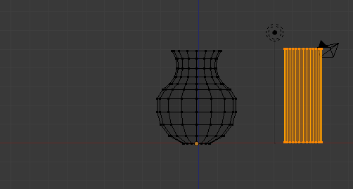
- Go to top view (7)

- Click on the Spin Button

- Open up the Spin menu, select Dupli and adjust angle to 360 and reduce the number of cylinders

- You'll end up with an extra cylinder and you'll need to remove it
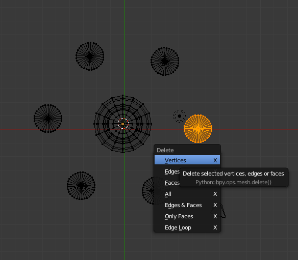
-
Add cylinder. Using the tool shelf, make the cylinder the width and height of the vase.
Rounded Corners
- Go to Front View
- Press Num 5 to switch out of perpective mode.

- Add a mesh plane (SHIFT+A).

- Tab to go to Edit Mode
- Delete the upper right corner by selecting it and pressing X.
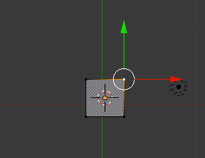
- Press B for border select and drag over the 3 vertices
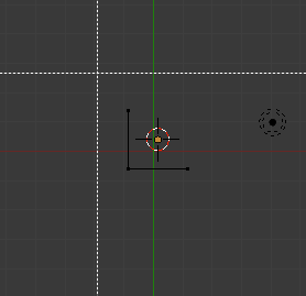
- Move the 3D cursor to the lower left corner
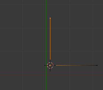
- Select the two left vertices

- Spin.
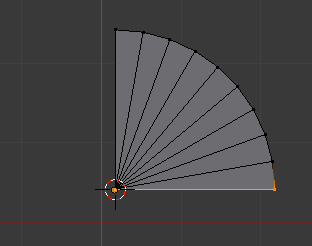
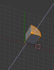
- Go to a side or front view, select all and extrude by pressing E and then Z. Extrude along the z axis.
Screw
- SHIFT+A add circle
- Press
R X 90
-
Hit TAB to go to Edit Mode
-
Press SHIFT drag along red
-
Add Modifier Screw
-
Change axis if needed
-
If you see weird lines click on calculate
-
Angle controls number of times to turn
-
Adjust Screw
Loft
The Loft tool is turned off as the default. To use it open User Preferences>Add-Ons>Mesh>LoopTools
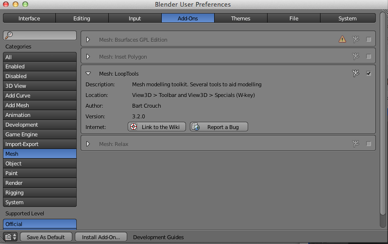
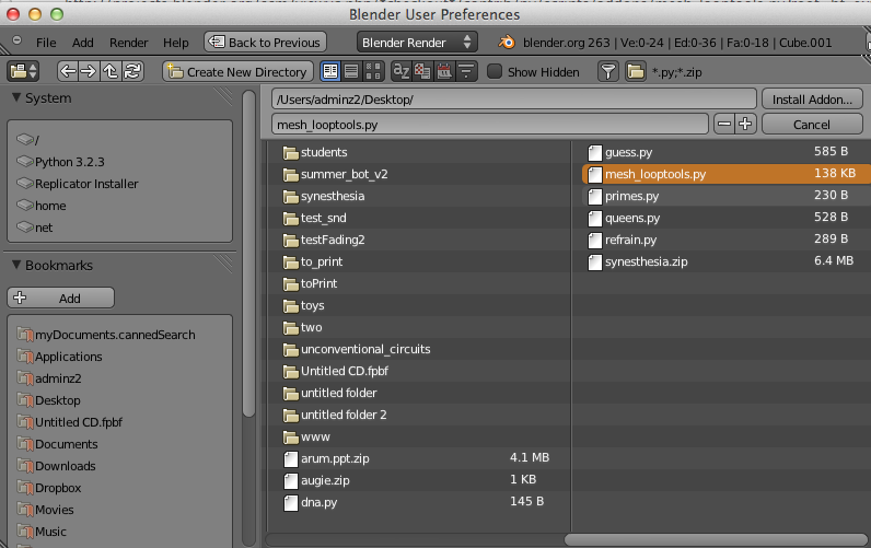
If you don't have the LoopTools option go to this page, download the python script (put it in a convenient place). Click on install AddOn
Install the AddOn
Enable it
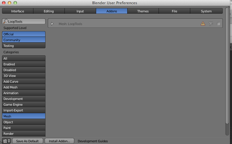
Click as Save As Default
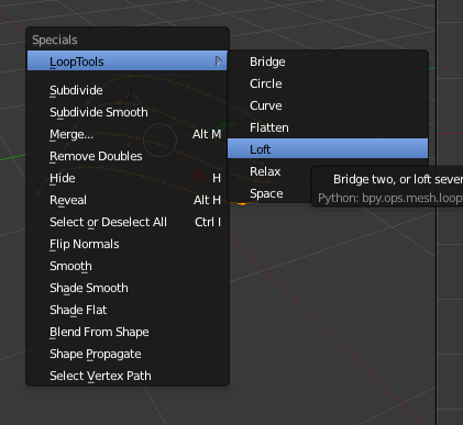
To use the Loft tool you must be in edit mode. Select the vertices and press W, then Loop Tools and Loft.
You need to make sure that your shape in Manifold (water-tight).
Select SHIFT+CTRL+ALT M if anything is selected go to Object mode and apply a Solidify Modifier
Return to edit mode and reselect SHIFT+CTRL+ALT M. Still a problem? Try recalculating normals and try again.
- Add a bezier curve and adjust the curve in edit mode
- Back in Object mode, make a duplicate (SHIFT+D). Edit the curve in Edit mode
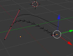
- Dupe and edit a few times
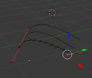
- In Object mode convert each curve to a mesh
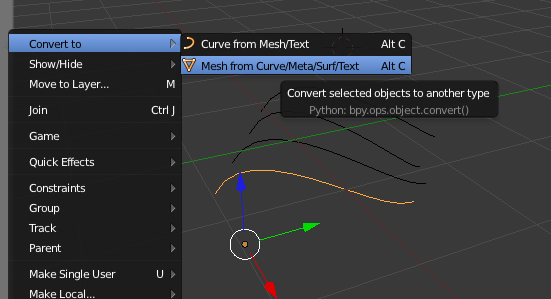
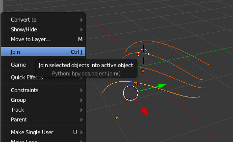
- Select the separate meshes and join them (CTRL+J)
- InEdit mode select all the vertices (A), press W and select Loop tools and Loft
- In Object Mode add a Solidify modifier
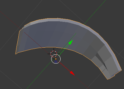
- In Edit mode check for Non-manifold SHIFT+CTRL+ALT M.
- If something is selected try Recalculating Normals
- Retry SHIFT+CTRL+ALT M
