Pulleybot by Printeraction
What is it?
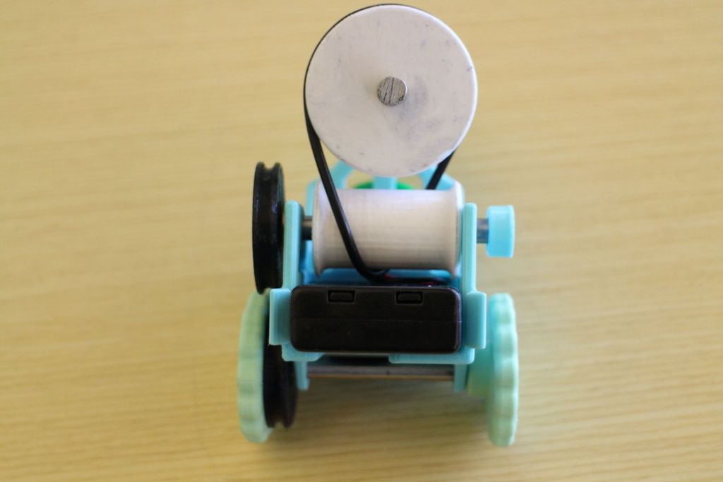
The PulleyBot is a 3D printed toy designed by Olin engineering student Alex Crease. It has a single actuator (motor) and a mechanical belt and pulley system transmission. A belt is a loop of material—a bike chain, a rubber band, a tank tread— that is used to transmit mechanical power. The belt is looped around sets of pulleys, wheels with grooves or teeth in them to catch the belt. As a pulley rotates about an axis, it drives the belt via friction between the belt's surface and the groove of the pulley. This in turn drives the other pulleys linked to the same belt. This lesson is derived from Printeraction's Instructable PulleyBot An Pulley Driven RobotParts
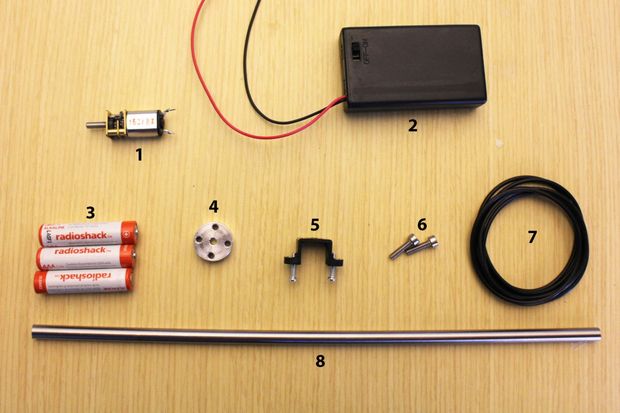
PulleyBot-An-Pulley-Driven-Robot
- Pololu Micro Metal Gearmotor 1000:1
- 3 AAA Enclosed Battery Pack with on/off switch
- 3 AAA batteries
- Pololu Universal Hub for 3 mm shaft with 4-40 Holes
- Pololu Micro Metal Gearmotor Bracket
- Pololu Micro Metal Gearmotor 298:1 or 1000:1
- 2 4-40 Socket Head Cap Screws
- Pack of 2 inch ID, 1/8th thick O-Rings
- 1 foot of .25 diameter D profile rod stock
- 1 3 inch
- 2 2.3 inches
- 1 2.1875 inches
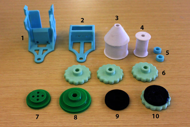
PulleyBot-An-Pulley-Driven-Robot
Gather your 3D printed parts:
- 1 Back_Chassis: Large, fancy piece with the cutout of the motor in the back, and various holes for shafts
- 1 Front_Chassis: Smaller fancy piece with various holes for shafts
- 1 Large_Drum: Large cylindrical piece with a conical top
- 1 Small_Drum: Small cylindrical piece
- 2 Hubcap: Short shaft caps that have the profile of the D-shaft in them
- 3 Wheel: Textured wheels with D-profile hubs.
- 1 Drive_Pulley: Double-grooved pulley with holes on its face
- 1 Speed_Shifter_Pulley: Double-grooved pulley with a hub sticking out of its top
- 1 Wheel_Driver: Pulley with no external hub and a single groove
- 1 Drive_Wheel: Pulley with a groove on one side and a textured wheel on the other.
Instructions
This lesson is derived from Printeraction's Instructable PulleyBot An Pulley Driven Robot- Gather and organize your parts.
- Place the batteries inside the battery holder.
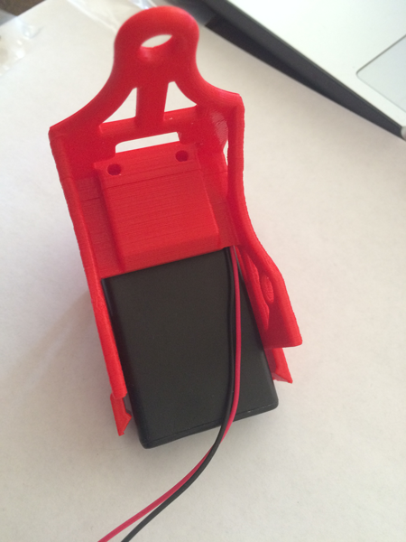
- Slide the battery box into the back of the Back_Chassis piece. Slide it in with the power switch facing down and toward the back of the chassis. You'll notice on the bottom of the that there is a nice slot to give the switch clearance.
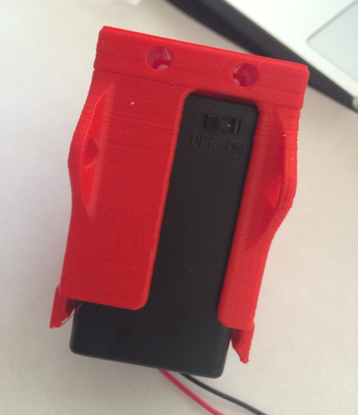
- As you slide the box in, make sure the wires are within the small channel on the top right side of the Back_Chassis enclosure. You need to keep the wire in this position to prevent them from getting damaged in the chassis.
- Find your motor.
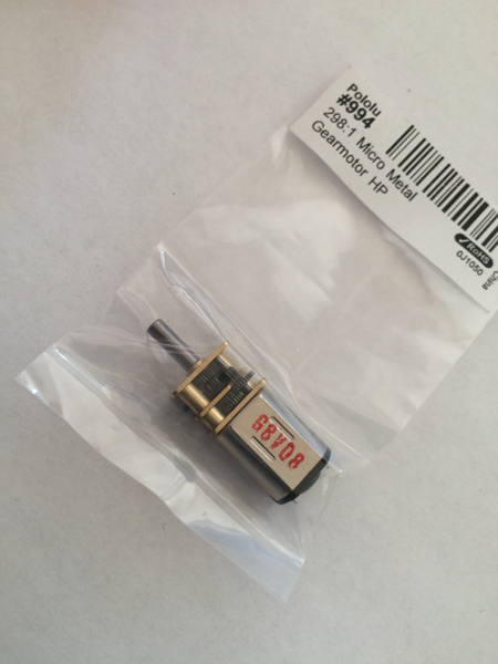
- If you ordered the bracket they come in a package of 2. You will only need 1. Each bracket comes with 2-56 mounting bolts and nuts.
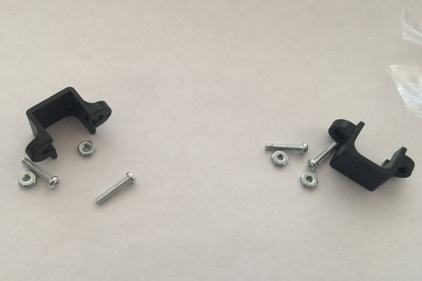
-
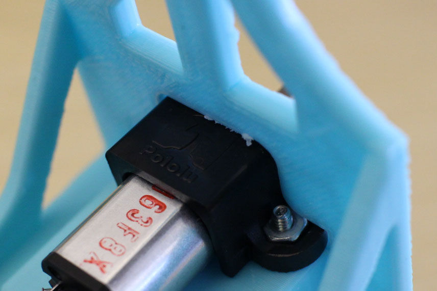
Place the motor bracket on top of the motor's gearbox (with the top of the Pololu logo toward the motor shaft).
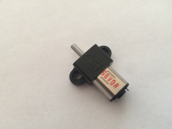
- Place the two nuts into their cavities on the bracket
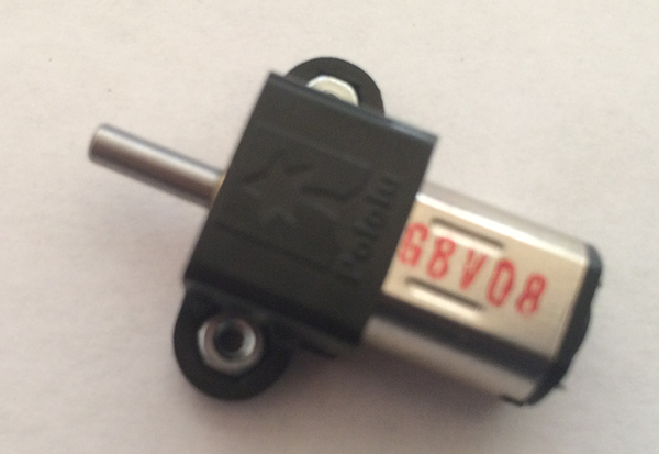
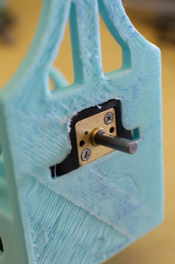
- Slide the bracket and motor into the bracket-shaped hole on the back of the chassis. The motor and bracket should be flush with the back face.
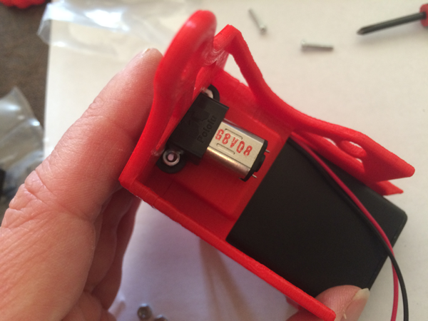
- Place the two bolts up through the holes in the bottom of the chassis and use the screwdriver to screw them into the nuts and tighten everything down.
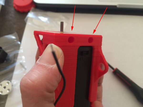
Hint: place your fingers over the nuts as you turn the part upside down:
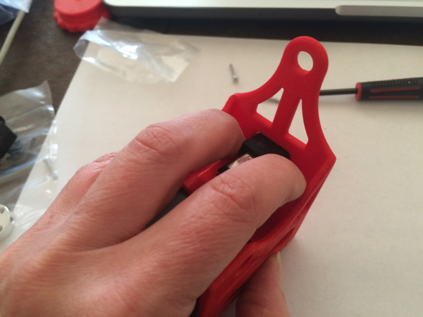
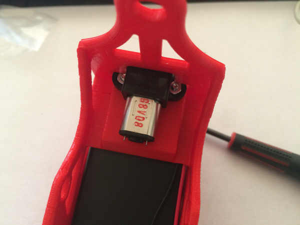
- Solder the battery box wires to the motor leads. It doesn't matter which wire goes to which lead, because you can change the direction of spin mechanically with the pulleys later on.
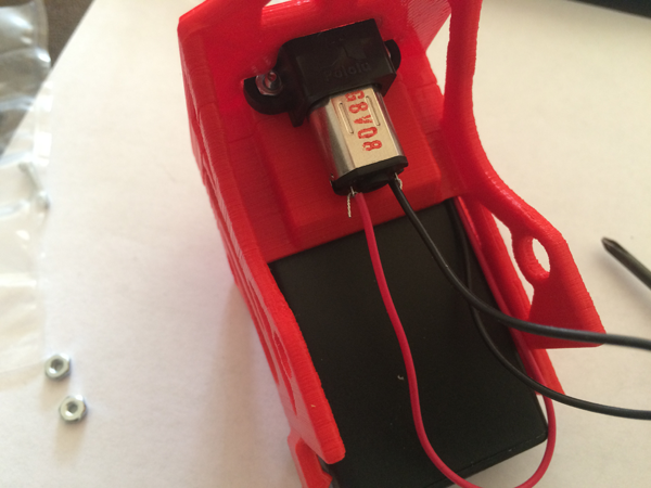
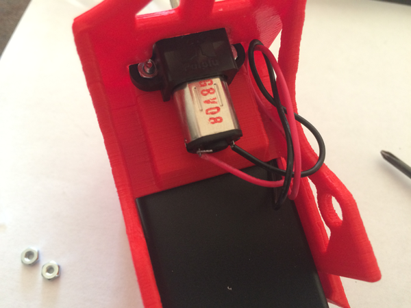
- Fold wires up in right corner so that they will not interfere with the belt and pulley system:
- Flip the on switch on the battery holder and make sure your motor is working properly. After it turns on, turn it off.
- Although each pulley has a close fit with the axle, there is still a chance the pulley may fall off the shaft. You'll want to superglue the following pulleys and shafts together to ensure a secure connection:
- Speed_Shifter_Pulley to 3" shaft
- Wheel to 2.3" shaft (X2)
- Wheel_Driver to 2.1875" shaft
Note: Don't apply too much glue. If you do, it will flow up and onto the shaft above the wheel, and this will make the fit between the shaft and the axle holes tighter and harder to turn, which is not a good thing! Just add a small dab of glue to the bottom of the hole in the pulleys.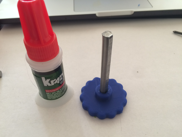
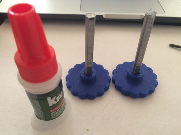
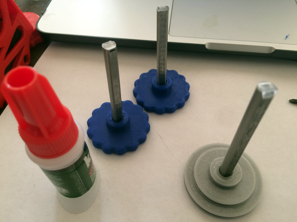
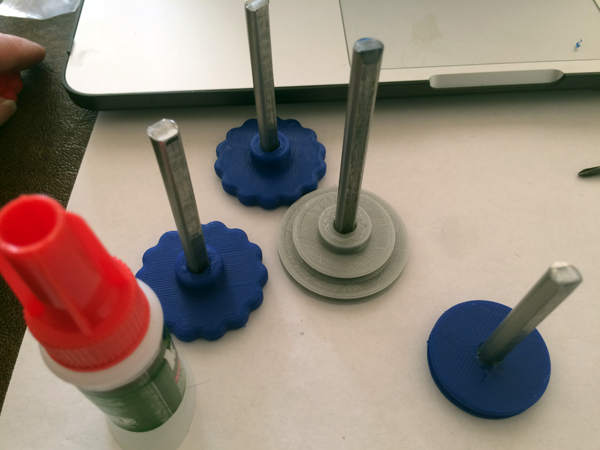
- Apply a very small amount of grease to the bars. Greased joints will ensure a smooth rotation once everything is assembled, and prevent anything from catching.
- Slide the Wheel_Driver (a flat pulley with no extended hub) pulley and shaft through ONLY the right (looking at the chassis from the back) of the two holes on either side of the top of the Back_Chassis piece.
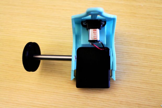
PulleyBot-An-Pulley-Driven-Robot - Before sliding the axle all the way through to the second hole, put the Small_Drum piece with a single O-ring around it between the two holes, and slide the axle through it until it comes out the other side of the chassis.
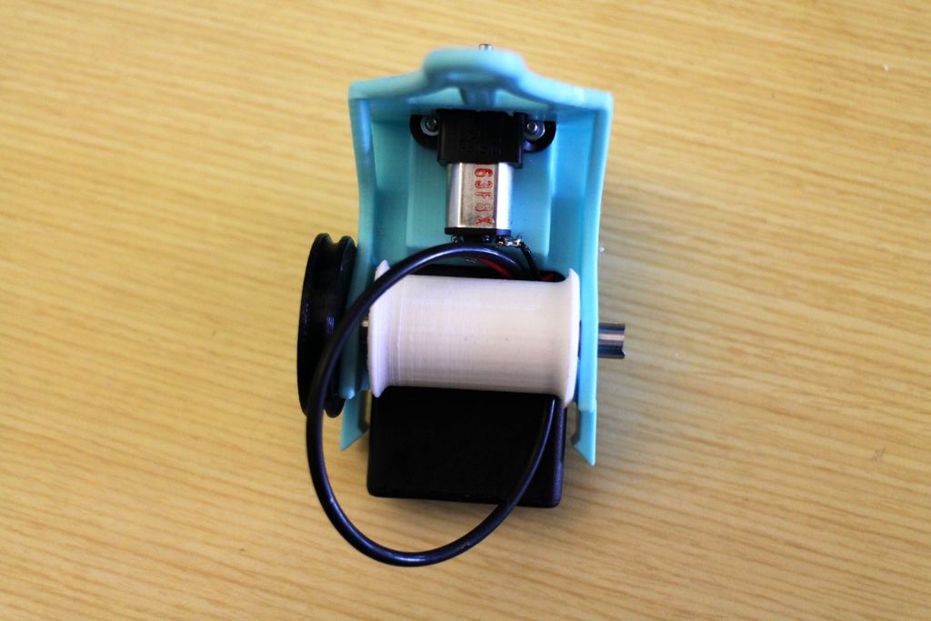
PulleyBot-An-Pulley-Driven-Robot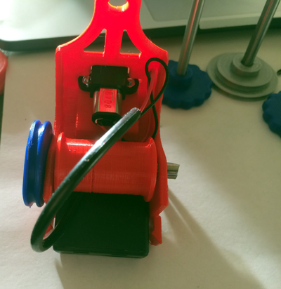
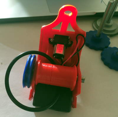
- Once the axle is all the way through, place the Hubcap piece on the exposed end of the shaft. Add a dab of superglue to a hubcap piece and secure it to the other end of the shaft.
- Slide the two wheel and axle parts you glued together into the holes along the bottom of the front and back chassis pieces. Put them in on the left side (looking from the back of the chassis). Add a dab of superglue to the inside of the Drive_Wheel piece, and attach it to the back axle shaft on the left side of the machine. Do the same with the last Wheel piece on the front shaft.
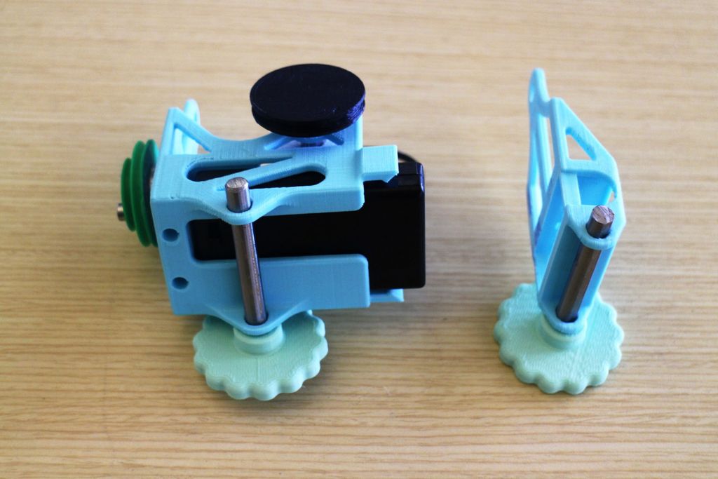
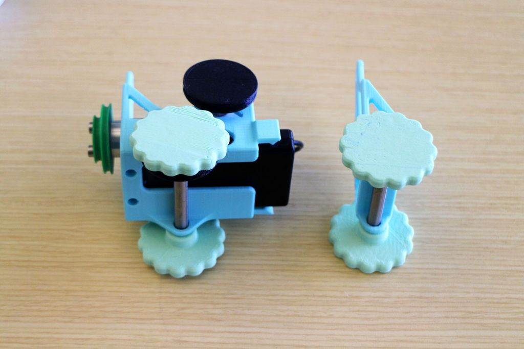
PulleyBot-An-Pulley-Driven-Robot
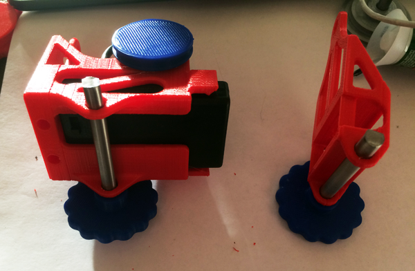
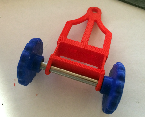
- Locate the motor hub and Drive_Pulley :
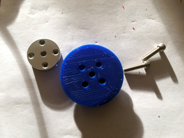
-
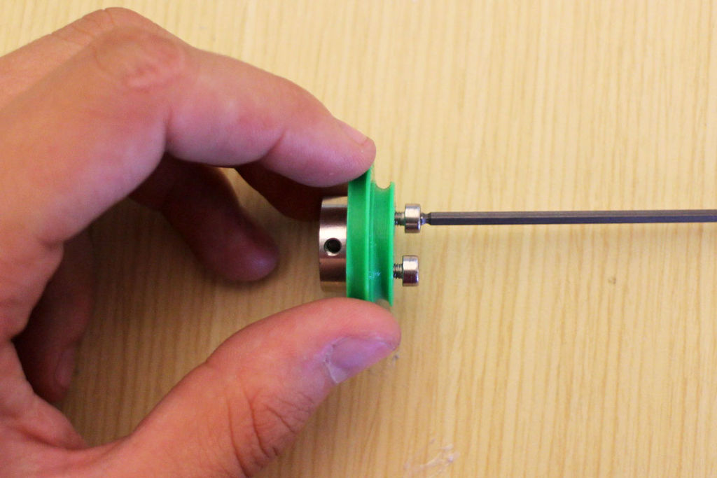
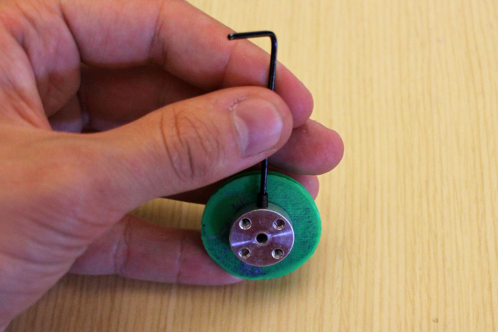
Place the Drive_Pulley piece on top of the motor hub, with the large side flush with the hub. Place the 4-40 screws into opposite holes in the pulley and screw them into the hub with the 3/32 hex wrench.
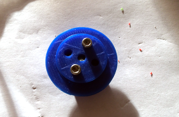
- Once this is complete, take one of the set screws that came with the hub and thread it into the hole on the side of the hub with the .05" hex wrench.DO NOT tighten all the way.
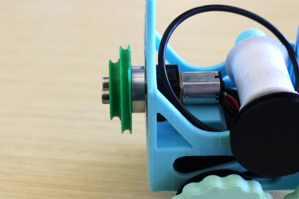
PulleyBot-An-Pulley-Driven-Robot - Before tightening it all the way, slide the hub and pulley onto the motor shaft as far as they can go (hub first), and align the set screw hole with the flat face of the shaft.
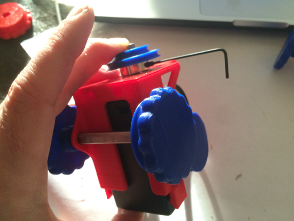
PulleyBot-An-Pulley-Driven-Robot - Now tighten the set screw with the small hex wrench:
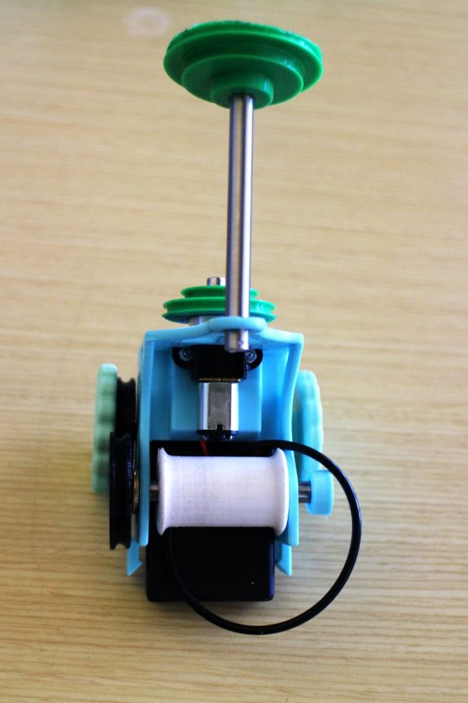
- Take the Speed_Shifter_Pulley and axle and only slide it into the back hole of the chassis. Place the Large_Drum piece between the two chassis pieces, and loop the O-ring attached to the Small_Drum around it while you do it.
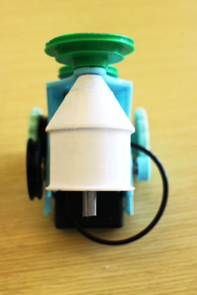
PulleyBot-An-Pulley-Driven-Robot
- Now it is important to note which direction you want your bot to move. Turn on the motor and see which way it turns. The axle with the Large_Drum will spin the same way. You want the Small_Drum axle to spin toward the front of the bot (clockwise when looking at the Tread_Driver piece), because this will spin the wheel forward. As the Large_Drum rotates, you'll want the side of the O-ring that it is "pulling" to come up the back of the Small_Drum. Twist the O-ring as necessary to ensure this (either you'll be twisting it 90 degrees to the left or right).
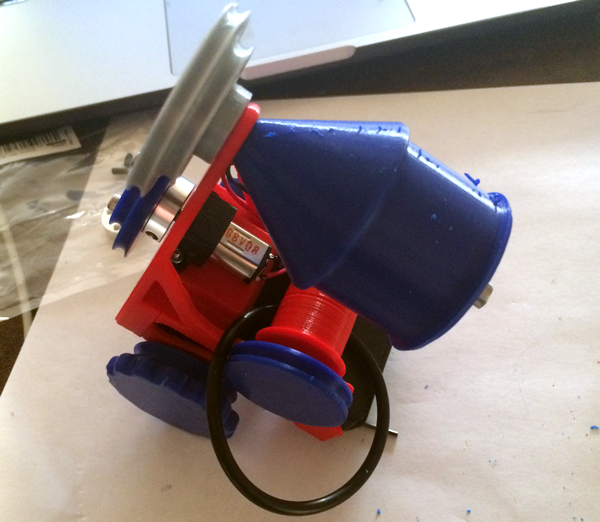
- Slide the Front_Chassis piece onto the battery box, largest face first. Make sure that the axle on the top of the bot slides through the hole on the face of the Front_Chassis piece. There are snap-fit joints on either side of the Back_Chassis piece, and you may need to spread them a little with your fingers as you slide the Front_Chassis part on. They will bend around the slight insets in the sides of the part and snap into the holes above the insets. Once each hook clicks into each hole, the entire chassis should be secure.
Put a second hubcap on the tip of the Large_Drum axle to secure it. You may not want to superglue this part down just because you may still want to access the battery box.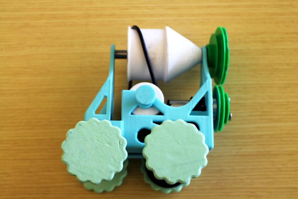
PulleyBot-An-Pulley-Driven-Robot - Loop the second O-ring around the smallest radius groove in the Drive_Pulley and the largest radius groove in the Speed_Shifter_Pulley.
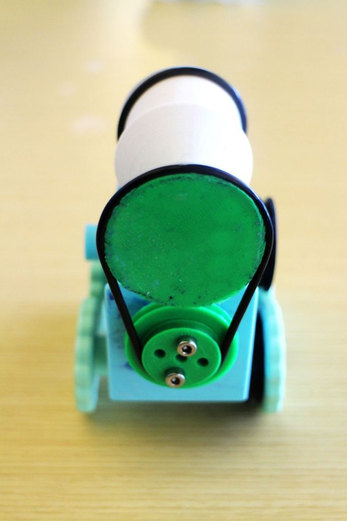
PulleyBot-An-Pulley-Driven-Robot - Slide the last O-ring around the back right Drive_Wheel piece and loop it to the Wheel_Driver. You'll want to loop it over the wheel before looping it around the Wheel_Driver.
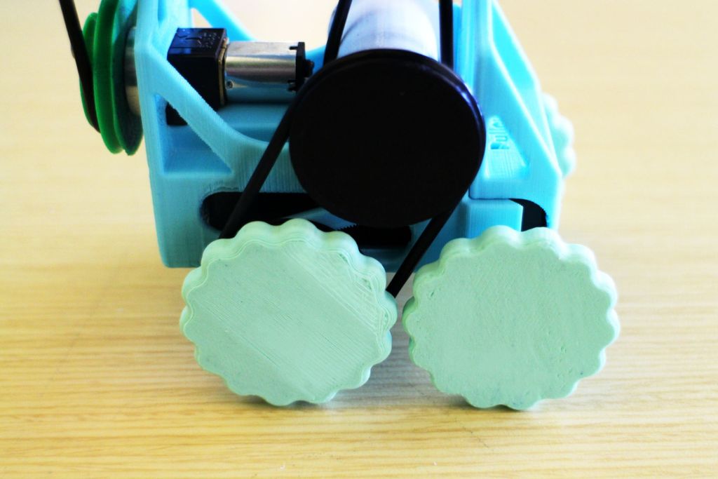
PulleyBot-An-Pulley-Driven-Robot - Turn on your Pulleybot. See if it moves. If it doesn't, ensure that the O-rings aren't slipping. If they are slipping, grease the axles around their pivots in the chassis.
- Notice the pulleys in the back have two different grooves with different radii. You can use these to change the speed and torque output of the bot. These systems are common on variable speed machines like lathes, drill presses, and milling machines.
The grooves on each "set" of aligned pulleys are dimensioned for the specific band length. Only place the O-rings over grooves that are aligned. The outermost set will make the Pulleybot move the slowest. The radius of the top pulley is larger than the bottom, so you end up with a 2:1 ratio it takes 2 rotations of the bottom pulley to turn the top pulley once). The other grooves have a 1:1 ratio. The pulleys spin at the same speed.
To change the speed, pull up on the O-ring near the pulley with the larger groove radius, and move it down to the adjacent smaller radius. Next, pull the O-ring near the other pulley from its current groove onto the next larger one, spinning the pulley as you do so.
If you want the bot to drive backward, twist one side of the O-ring 180 degrees before placing it in the groove. This will make the top pulley spin in the opposite direction of the bottom one.
Challenge
How can you change the Pulleybot?- Wheel size?
- Using different pulleys with different size O-rings?
- What else?
center hub
- height=6
- hole diameter=6.43
- wall thickness=3.15
- filletedge=.5
pulley
- 33.3321 bottom and top cylinder diameter
- 1.7 height of bottom and top
- 30.21 middle cylinder diameter
- 2.98 middle height
- filletedge=1
- chamferedge dist 1=1, distance 2=.5
wheels
- diameter=41
- height=6.03
- filletedge .5
hubcap
- outer diameter=12.56
- height=6.35
- hole depth=4.65
large drum
- 37.51 diameter
- 24 height
- cone diameter: bottom=41 top=10.7
- 30 cone height
- rim height=2.15
- rim diameter 40.32
- chamfer to bottom 1
AutoCad Setup
When using the Command Line, AutoCAD expects you provide information in a very particular order. As you enter information you will see that the command line will provide prompts for the information that the program requires to continue. Watch the command line and follow the prompts.You do not have to place the cursor in the command line field. Just start typing and the text will appear in the field. If you need to get out of a command, press ESC.
- Launch AutoCAD.
- Create a new drawing. Select File>New Drawing:
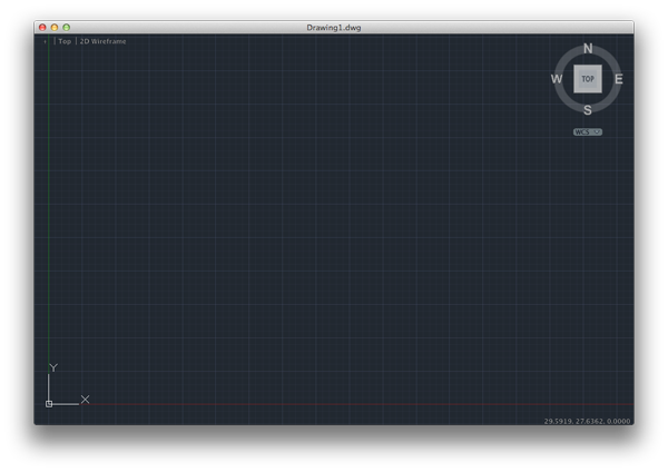
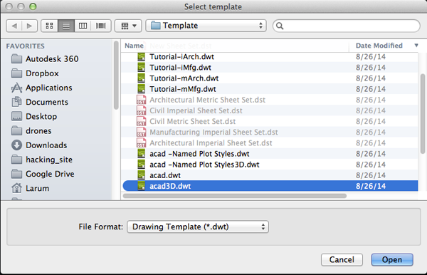
- Select acad3D.dwt template file and press the Open button to continue to the drawing screen.
- Find the commandline.

If it is not present you should be able to open it it by selecting Window> Command Line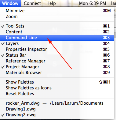
Other ways to display the command line are:
• Pressing Command+3 on Mac, CTRL+9 on Windows.
• Pressing F2
•Typing COMMANDLINE or CLI - You want to set your units to millimeters. Type UN and select UN (UNITS):
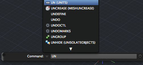
or select Format>Units from the top menu to bring up the Units Dialog box.
Set your units to millimeters: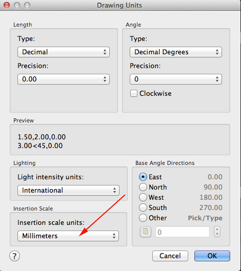 .
.
- You want to create a resolution appropriate for 3D printing. Type FACETRES and set it to 10.
- Make sure your profiles are not deleted after you use them. Type DELOBJ. Set the value to 0.
- In the top left corner set the Custom Visual style to Wireframe or Shaded with Edges.
- Autodesk, like Photoshop has layers. Type LAYER (LA) to initiate the command
or select Window>Layers or press Command+4 (Mac):
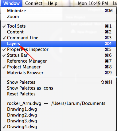
This will bring up the Layer Properties Manager Palette: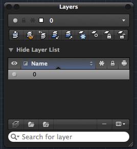
- Click the New Layer Button.
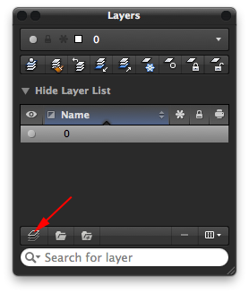
- Name the new layer center hub (press <RETURN> after typing the name in the field).
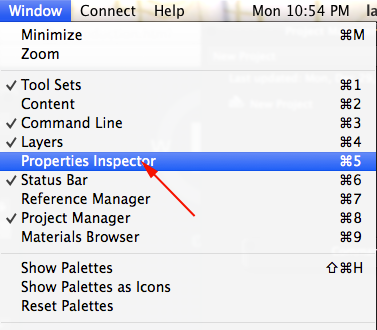
- Type Properties or PR to open the Properties Inspector
or select Window>Properties Inspector or press Command +5 (Mac)
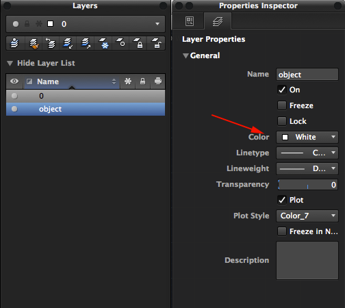
- In the Properties Inspector make the layer's color white:
- To move objects to a particular layer, select your object or objects or drag a box around them (if you drag from left to right (→), your selection must include every line. If you you drag from right to left (←) you just need to include part of every segment).
Look for the Layer Properties Manager Palette. There is a drop-list there with your layer names. With your objects selected, change the layer to object.
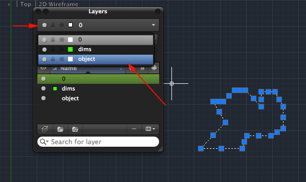
Press the ESC key. If all went well, your object will now be on the selected layer. - To close the Properties Inspector type PROPERTIESCLOSE.
- To save your drawing type SAVEAS and save your drawing either in your work folder or on the desktop. Make sure to name your drawing so that you can find it later.
OSNAPs
If you want to draw a line from the CENTER of a circle to the middle of a vertical line, AutoCAD has a feature that makes this very easy. The feature is called Object Snaps (or Osnaps pronounced "Oh-Snaps").
Image from onikage108.deviantart.com ©2011-2015 katarnlunney
There are a few ways to enable OSNAPS. First you can type OS and press <RETURN>. You will see a dialog box:
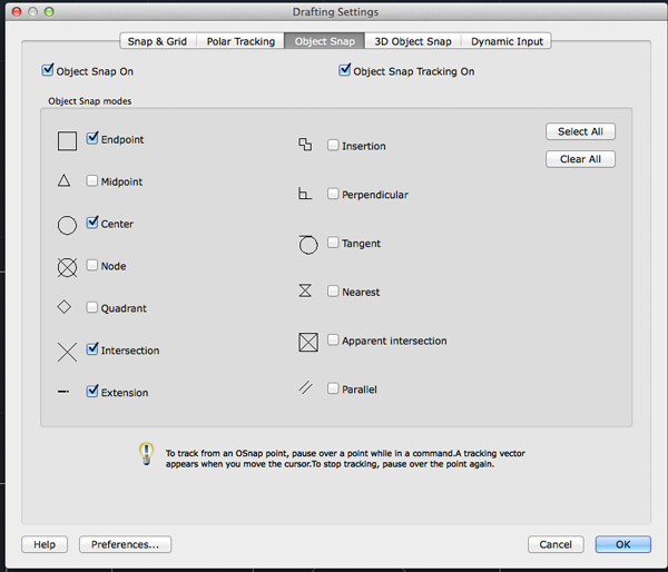
You may select whichever points you want to 'snap' on an object.
Another way is to enable OSNAPS is using the status bar. CTRL+click on the Object Snap icon and then select the OSNAP/OSNAPS you want to enable.
 .
.
OSNAPS are on when the icon is enabled:
 .
.
Another way is to press F3 for 2D OSNAPS and F4 for Object Snap Tracking . Object Snap Tracking works with OSNAP and POLAR to help align new points with existing locations in your drawing.
You can also select the OSNAP using the command line.
Creating the center hub
- height=6
- hole diameter=6.43
- wall thickness=3.15
- filletedge=.5
- Type C for Circle.
- Set the center of your circle to 0,0 by typing 0,0 and pressing RETURN.
- Type D for diameter and press RETURN.
- Type 6.43 and press RETURN.
- Zoom in by typing Z and pressing return and then typing E and pressing RETURN.
- Turn on OSNAPS. Make sure Quad is enabled.
- Type L for line and and snap to the top and bottom of the circle:

- Type Div for Divide and press RETURN. Click on the line, type 5 and press RETURN.
- Type DDPTYPE and change the percentage to 25%.
- Enable ORTHO:

- Type L for line and and snap to the bottom point on the line.
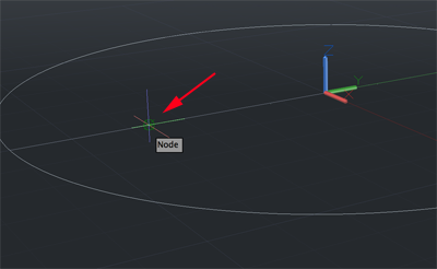
- Draw the second point of the line outside the circle:
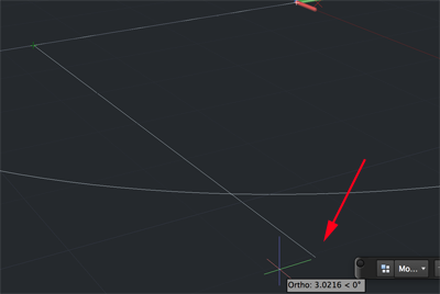
- Type MIRROR and press RETURN. Select the line you just drew and press RETURN. Click on the both points of the line bisecting the circle and press RETURN:
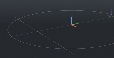
- Type OFFSET and press RETURN. Type 3.15 and press RETURN. Click on the circle then click outside the circle and press RETURN. Pres ESC to clear the commandline.

- Type TRIM and press RETURN. Select both lines (the one that was mirrored and the the mirrored line). Press RETURN. Click on the smaller curve on the other side of these lines and the bisector on the same side of the smaller curve. Press RETURN:
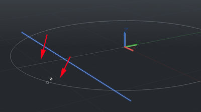
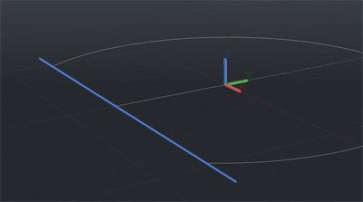
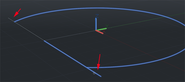
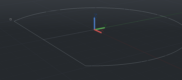
- RIGHT click to select TRIM again. This time click on the curve. Press RETURN. Click on both lines where they extend beyond the curve. Press ESC to clear the Commandline.
- Click on the cinner circle's vertical bisector and the points and delete them.
- You need to make the inner shape one line. Type PE to call the PEDIT command. Press RETURN. Type M and press RETURN. Click on the curve and the two lines. Press RETURN. Type J to join and continue to press RETURN until the commandline is clear. TURN. Move the cursor between the two curves until they are both highlighted then click:
- Type 6 and press RETURN:
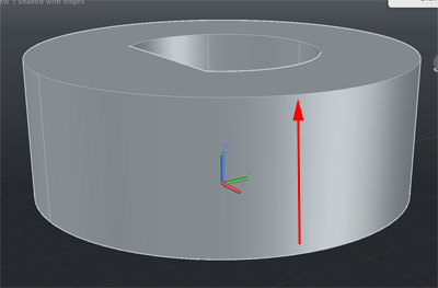
- Type FILLETEDGE and press RETURN. Type R and press RETURN. Type .5 and Press RETURN. Click on the top edges and press RETURN until the commandline is clear.
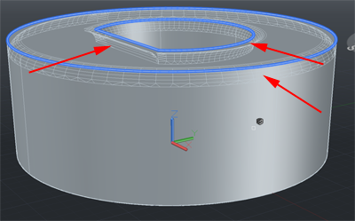
- If you don't have a layer named center hub, create one now. Move the form onto that layer.
- Turn off the center hub layer.
- Create a new layer named profiles.
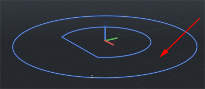
- Move your lines onto the profile layer.
- Turn off your profile layer.
- Save the file.
Basic Wheel
- diameter=40.35
- height=5.97
- filletedge .5
- Bumps 14
- Type C for Circle.
- Set the center to 0,0 and press RETURN.
- Type D for diameter and press RETURN.
- Type 40.35 and press RETURN.
- Open the Properties Inspector (Under Window menu).
- Click on circle and look for the circumference.
- Open a calculator
- Divide the circumference by 14. In this case the answer is close to 9.
- Type C for circle.Press RETURN. Type 2P for a circle made by specifying 2 pts. Pres RETURN. Click on the point of the circle that falls on the x axis. Now type @9,0 and press RETURN.
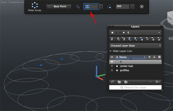
- To get 14 circles type ARRAY and press RETURN.
- Select the circle and press RETURN.
- Type PO for Polar and press RETURN.
- Type 0,0 and press RETURN to specify center.
- In the dialog box enter 14 for Number of Items.
- Click on the x to accept.
- Click on the circle and delete it.
- Type EXPLODE. Press RETURN. Click on one of the 14 circles. This will allow you to edit the curves.
- Type TRIM and press RETURN. Select all the circles and press RETURN.
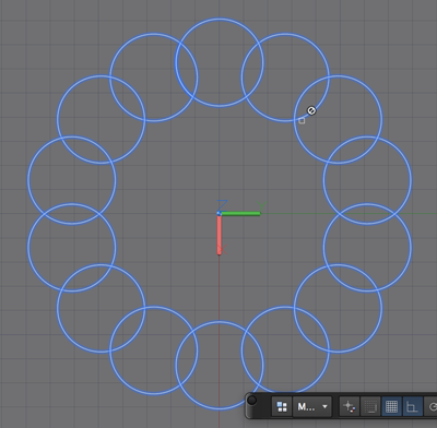
- Now click on all the inner curves so that all that remains is the outside. You probably won't be able to trim the original circle. Don't worry, you can come back to this after.
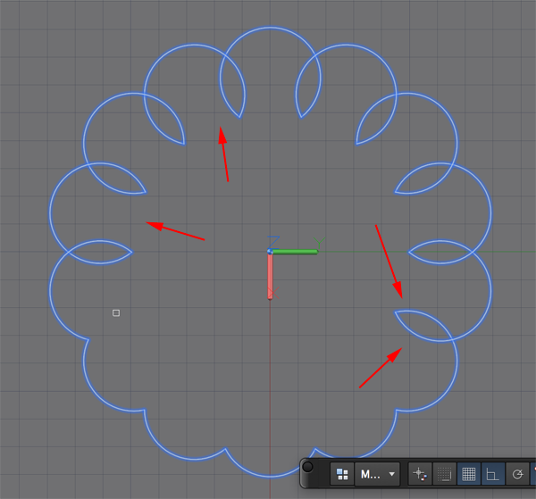
- You need to join the curve. Call PE for PEDIT and press RETURN.
- Type M for multiple and type RETURN.
- Select all the curves and press RETURN.
- Press RETURN to Convert.
- Type J and press RETURN until the commandline is cleared.
- Type FILLET and press RETURN. Type R and press RETURN to set the radius. Type .5 and press RETURN. Type M for multiple ad press return. Click on each of the two lines where they meet.
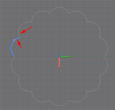
- Type PRESSPULL and press RETURN. Click on the curve and type 6. Press RETURN.
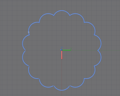
- Call FilletEdge and press RETURN.
- Type R and press RETURN.
- Type 1 for the radius and press RETURN.
- Type L for loop and press return. Click on an edge. If it is not the edge you want type N for next and press RETURN. When the edge is correct press REURN until the edge is filleted.
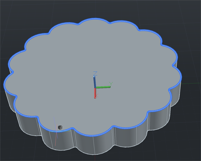
- Repeat for the bottom edge.
- Turn on the center hub layer.
- Set the view to WIREFRAME.
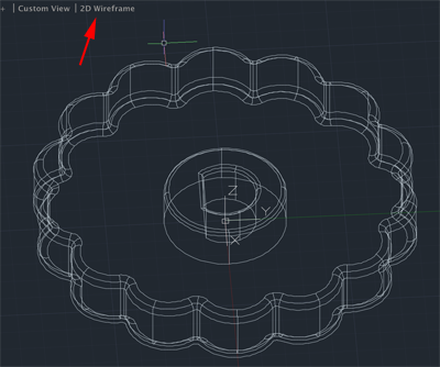
- Type M for MOVE and press RETURN. Click on the hub and press RETURN. Select the first point as the bottom center then type @0,0,6 and press RETURN.
- Set the view to Shaded with edges.
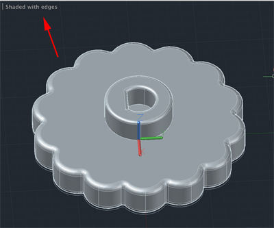
- Save.
